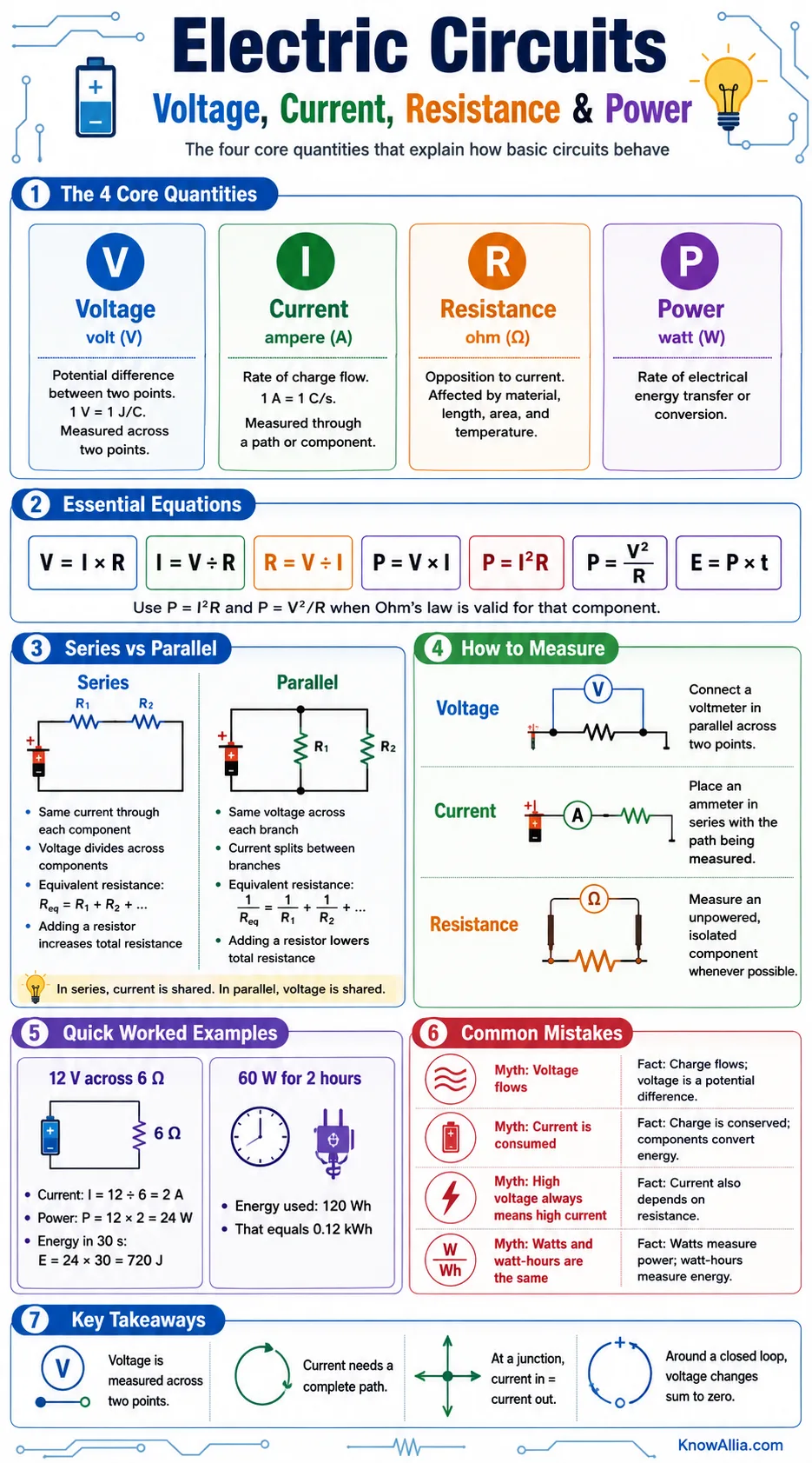
An electric circuit is a connected path in which electric charge can move and electrical energy can be transferred. Four quantities describe most basic circuit behavior: voltage is the electric potential difference between two points, current is the rate of charge flow, resistance describes how strongly a component opposes current, and power is the rate at which electrical energy is transferred or converted.
What These Four Quantities Tell You
Voltage, current, resistance, and power are related, but they do not describe the same property. A circuit calculation becomes much easier when each value is attached to a specific component, branch, or pair of points.
- Voltage is measured across two points.
- Current is measured through a path or component.
- Resistance and circuit arrangement determine how current and power are distributed.
This article explains the physical meaning of each quantity, the equations that connect them, the differences between series and parallel circuits, correct meter placement, common misunderstandings, and the limits of ideal circuit models.
What Makes a Circuit Work?
A basic circuit needs a source, a conducting path, and at least one component that receives or converts energy. The path must be closed for a steady direct current to continue. An open switch interrupts the path, so current falls to zero in that branch even though a voltage may still exist across the open gap.
Source
A battery, generator, or regulated supply maintains a potential difference. A source provides energy to charges; it does not create charge from nothing.
Conducting Path
Wires and conductive traces connect components. Ideal diagrams often treat wires as having zero resistance, while real conductors always have some resistance.
Load or Component
A resistor, lamp, motor, sensor, or electronic circuit converts electrical energy into heat, light, motion, sound, stored energy, or another useful form.
A circuit diagram is a map of electrical connections rather than a picture of physical placement. Two points joined by an ideal wire are treated as the same node and therefore have the same electric potential.
Voltage: Energy Difference per Unit Charge
Voltage, also called electric potential difference, tells how much electric potential energy changes per unit charge between two points. One volt is one joule per coulomb. Voltage is represented by V or sometimes by ΔV, and its SI unit is the volt.
Voltage is never a property of one isolated point. A statement such as “this node is 5 V” means that the node is 5 V relative to a chosen reference point, often called ground or 0 V.
A voltage source can maintain a difference in potential even when no current flows. An unused battery, for example, may show a terminal voltage on a voltmeter while the circuit remains open. Once a load is connected, the source voltage helps establish an electric field throughout the circuit, and charge already present in the conductors begins to drift.
- Choose two points.
- Assign the measurement direction from the first point to the second.
- State the result with polarity, such as +5 V or −5 V.
The sign depends on the chosen order of the two points. Reversing the voltmeter leads reverses the sign but does not change the physical circuit.
Current: The Rate of Charge Flow
Electric current is the rate at which charge passes a point or crosses a defined surface. It is represented by I, and its SI unit is the ampere. One ampere equals one coulomb of charge per second.
In circuit diagrams, conventional current is drawn in the direction positive charge would move: from higher potential toward lower potential through a passive component. In metal wires, the mobile electrons drift in the opposite direction. Both descriptions refer to the same current and produce the same circuit calculations.
Current is not used up by a component. Charge entering a steady-state component leaves at the same average rate. What changes is the electrical energy carried per unit charge, which appears as a voltage drop across an energy-absorbing component.
Current requires a complete path, but that path may contain branches. At a junction, the total current entering equals the total current leaving. This charge-conservation rule is commonly called Kirchhoff’s current law.
Resistance: Opposition to Current
Resistance relates the voltage across a component to the current through it. It is represented by R and measured in ohms, written with the symbol Ω. One ohm equals one volt per ampere. NIST lists the SI relationships among the volt, ampere, watt, and ohm on its electrical units page.
For a uniform wire, resistance depends on the material, length, cross-sectional area, and temperature. A longer wire usually has more resistance because charge carriers encounter a longer path. A wider wire usually has less resistance because it provides more conducting area.
- Material: Different materials have different resistivities.
- Length: Greater length raises resistance when other properties stay fixed.
- Area: Greater cross-sectional area lowers resistance.
- Temperature: Resistance may rise or fall with temperature, depending on the material.
Resistance is not always a fixed number. A resistor designed for circuit use may remain close to its rated value over a limited operating range, while a filament lamp, thermistor, diode, and many other components show a changing voltage–current relationship.
Ohm’s Law and Its Proper Use
For an ohmic component operating under conditions where its resistance remains constant, voltage, current, and resistance are related by:
V = I × R
I = V ÷ R and R = V ÷ I are rearrangements of the same relationship.
Ohm’s law is highly useful, but it is not a universal rule for every electrical component. OpenStax notes that many materials do not maintain a linear voltage–current relationship, so the equation should be applied only when the component or model supports it. OpenStax: Ohm’s Law
A straight-line graph of voltage against current indicates constant resistance over the measured range. If the graph curves, the ratio V ÷ I changes with operating point. The component can still have resistance at a given point, but a single constant value no longer describes its full behavior.
How the Main Circuit Quantities Fit Together
Each quantity answers a different question about charge, energy, and circuit behavior.
V
Voltage · volts
How much electric potential energy changes per unit charge between two points.
I
Current · amperes
How much charge passes a point per unit time.
R
Resistance · ohms
How voltage and current are related in a resistive path or component.
P
Power · watts
How quickly electrical energy is supplied, absorbed, or converted.
The resistance-based power forms, P = I²R and P = V²/R, apply when Ohm’s law is valid for the component being analyzed.
Power and Energy Are Not the Same
Electrical power is the rate of energy transfer. It is represented by P and measured in watts. One watt equals one joule per second. For a DC component, or for instantaneous values, power is:
When Ohm’s law applies, substitution gives two additional forms:
- P = I²R when current and resistance are known.
- P = V² ÷ R when voltage and resistance are known.
These equations describe the same physical rate from different known values. OpenStax presents the connection among voltage, current, resistance, power, and energy in its section on electrical energy and power.
Energy is the accumulated amount transferred over time. If power remains constant, E = P × t. Joules are used in SI calculations; watt-hours and kilowatt-hours are also common. A 60 W device operating for 2 hours uses 120 Wh, which equals 0.12 kWh.
A useful analogy is a water system: voltage resembles a pressure difference, current resembles flow rate, resistance resembles a restriction, and power resembles how quickly the moving water can transfer energy. The analogy helps with basic relationships, but electric charge does not behave exactly like water, especially in capacitors, inductors, semiconductors, and AC circuits.
Series and Parallel Circuits
The way components are connected determines which quantity is shared and which quantity divides. Series components lie on one current path. Parallel components connect across the same pair of nodes.
| Property | Series Connection | Parallel Connection |
|---|---|---|
| Current | The same current passes through each component. | Branch currents may differ; their sum equals the source current. |
| Voltage | Voltage drops add to the source voltage around the loop. | The same voltage appears across each branch. |
| Equivalent resistance | Req = R1 + R2 + … | 1/Req = 1/R1 + 1/R2 + … |
| Result of adding a resistor | Total resistance rises. | Total resistance falls because another current path is added. |
| Power | Individual powers add to total absorbed power. | Individual branch powers add to total absorbed power. |
For parallel resistors, equivalent resistance is always lower than the smallest branch resistance. For series resistors, equivalent resistance is greater than any individual resistance in the chain. These rules and their derivations are shown in the OpenStax section on resistors in series and parallel.
Kirchhoff’s Two Circuit Rules
- Junction rule: Current entering a node equals current leaving it.
- Loop rule: The signed voltage changes around a closed loop add to zero.
The junction rule follows from conservation of charge. The loop rule follows from conservation of energy. Together they allow analysis of circuits that cannot be reduced by simple series and parallel combinations.
How Voltage, Current, and Resistance Are Measured
A multimeter changes its internal connection depending on the selected measurement. Correct placement matters because the meter becomes part of the circuit.
| Measurement | Meter Connection | Reason |
|---|---|---|
| Voltage | Connect the voltmeter in parallel across two points. | A voltmeter compares potential between its two leads and is designed with high internal resistance. |
| Current | Place the ammeter in series with the path being measured. | The branch current must pass through the meter; an ammeter is designed with very low internal resistance. |
| Resistance | Measure an unpowered, isolated component whenever possible. | The meter applies its own small test signal, and other circuit paths can alter the reading. |
Measurement safety: Introductory calculations and low-voltage educational circuits do not make mains wiring a suitable practice setting. Work involving building wiring, distribution panels, or unknown energy sources belongs with trained and properly qualified personnel.
A real voltmeter draws a very small current, and a real ammeter adds a small resistance. Good instruments are designed to reduce these effects, but no physical measurement is perfectly invisible to the circuit.
Worked Circuit Examples
Example 1: One Resistor on a 12 V Source
An ideal 12 V source is connected across a 6 Ω resistor.
- Current: I = V ÷ R = 12 ÷ 6 = 2 A.
- Power: P = V × I = 12 × 2 = 24 W.
- Energy converted in 30 seconds: E = P × t = 24 × 30 = 720 J.
The same power result appears from P = I²R: 2² × 6 = 24 W. Agreement between two valid methods is a useful arithmetic check.
Example 2: Two Resistors in Series
A 4 Ω resistor and an 8 Ω resistor are connected in series across 12 V.
- Equivalent resistance: Req = 4 + 8 = 12 Ω.
- Circuit current: I = 12 ÷ 12 = 1 A.
- Voltage across 4 Ω: V = 1 × 4 = 4 V.
- Voltage across 8 Ω: V = 1 × 8 = 8 V.
- Voltage check: 4 V + 8 V = 12 V.
The larger resistor receives the larger voltage drop because the same current passes through both resistors.
Example 3: Two Resistors in Parallel
A 6 Ω resistor and a 3 Ω resistor are connected in parallel across 12 V.
- Current in the 6 Ω branch: I1 = 12 ÷ 6 = 2 A.
- Current in the 3 Ω branch: I2 = 12 ÷ 3 = 4 A.
- Total current: Itotal = 2 + 4 = 6 A.
- Equivalent resistance: Req = 12 ÷ 6 = 2 Ω.
- Total power: P = 12 × 6 = 72 W.
The 3 Ω branch carries twice the current of the 6 Ω branch because both branches have the same voltage and the lower resistance permits more current.
Common Points of Confusion
“Voltage Flows”
Voltage does not flow. Charge flows, and voltage describes a potential difference between points.
“Current Is Consumed”
A component transfers energy from moving charge, but steady current does not disappear inside it. Charge is conserved.
“A Battery Supplies Fixed Current”
A voltage source does not normally force one current into every load. The connected circuit and the source’s internal limits determine current.
“More Resistance Means More Power”
The result depends on what is held constant. With fixed current, P = I²R rises with resistance. With fixed voltage, P = V²/R falls as resistance rises.
“Ohm’s Law Applies to Everything”
It applies directly to components with an ohmic, approximately linear relationship over the operating range being considered.
“Watts and Watt-Hours Are Interchangeable”
Watts measure a rate. Watt-hours measure energy accumulated over time.
Essential Circuit Terms
- Charge
- A physical property measured in coulombs. Electric current is the rate of charge flow.
- Node
- A set of connected points treated as having the same electric potential in an ideal circuit.
- Branch
- A path between two nodes containing one or more circuit elements.
- Potential Difference
- Energy change per unit charge between two points; another name for voltage.
- Resistivity
- A material property that helps determine the resistance of a conductor with a given length and area.
- Ohmic Component
- A component whose voltage is proportional to current over the operating range being studied.
- Equivalent Resistance
- A single resistance that draws the same total current as a resistor network at the same terminal voltage.
- Electrical Power
- The rate at which electrical energy is delivered, absorbed, or converted.
- Ground
- A selected reference node assigned 0 V. It is not automatically the same as physical earth in every circuit.
Where the Simple Model Stops
Basic resistor equations are accurate within their assumptions. They do not describe every effect found in a physical circuit.
- Sources have internal resistance. Their terminal voltage may fall when current rises.
- Wires are not perfect conductors. Long, thin, or warm conductors can have noticeable resistance.
- Component values have tolerances. A labeled resistance is a nominal value, not an exact guarantee.
- Temperature changes behavior. Heating can alter resistance and therefore current and power.
- Capacitors and inductors store energy. Their behavior depends on time and, in AC circuits, frequency.
- AC power may require more than P = VI using ordinary meter readings. RMS values, phase difference, and power factor can matter.
- Semiconductors are often nonlinear. Diodes and transistors cannot usually be replaced by one fixed resistance across all operating conditions.
Measured values also carry uncertainty from instrument accuracy, lead resistance, contact quality, temperature, and the meter’s effect on the circuit. A reported result should therefore match the precision of the equipment and the model.
Questions About Basic Electric Circuits
Frequently Asked Questions
What is the difference between voltage and current?
Voltage is an energy difference per unit charge between two points. Current is the rate at which charge moves through a path. Voltage can exist without a closed path, while steady current requires one.
Does high voltage always mean high current?
No. Current depends on the connected circuit. For an ohmic load, current equals voltage divided by resistance, so a high voltage across a very high resistance may produce a small current.
Why is voltage measured in parallel?
A voltmeter compares electric potential at two points. Connecting it across a component lets it measure that component’s voltage without intentionally interrupting the branch.
Why is current the same in a series circuit?
A series circuit has one uninterrupted path. In steady operation, charge cannot continuously accumulate inside a component, so the same rate of charge flow passes each point in the path.
Why is voltage the same across parallel branches?
Every parallel branch connects to the same two nodes. Since voltage is the potential difference between those nodes, each branch has the same voltage.
Can a component have voltage across it with no current?
Yes. An open switch can have a voltage across its terminals while current through the open path is zero. A charged capacitor can also maintain a voltage after charging, subject to leakage and other real effects.
When should P = I²R or P = V²/R be used?
Use those forms when Ohm’s law is valid for the component and the required current, voltage, and resistance refer to that same component. The more general electrical power relation is P = VI.
Is electrical power the same as electrical energy?
No. Power is the rate of energy transfer, measured in watts. Energy is the amount transferred over a time interval, measured in joules, watt-hours, or kilowatt-hours.
Sources
- Cornell High Energy Synchrotron Source – Discovering Ohm’s Law — Experimental treatment of voltage, current, resistance, circuit diagrams, and meter use.
- University of Colorado Boulder PhET – Circuit Construction Kit: DC — Interactive circuit modeling with batteries, resistors, switches, meters, and non-ohmic lamps.
- The University of Texas at Austin – Basic Electronics — University reference material on resistors, power equations, voltage, and current.
- The Open University – Voltage, Current and Resistance — Introductory explanation of Ohm’s law and the relationship among the three quantities.
- OpenStax Physics – Electric Power — Peer-reviewed textbook treatment of power in resistor circuits.